
The question asks about the characteristics of an ideal tool material. We need to evaluate each option based on the desired properties of cutting tools in machining operations.
Comparing the options, the ability to maintain consistent life across all cutting speeds points towards a material that is robust and versatile, which aligns best with the concept of an "ideal" tool material, even if practically unachievable.
Correct Option: B) Has same life at all cutting speeds
The question asks about the primary purpose of using chills in casting molds. Chills are metallic inserts placed in sand molds to accelerate the cooling rate of specific sections of a casting. Understanding their function is key to answering this question.
Correct Option: A) Achieve directional solidification. Chills are specifically used to increase the cooling rate in certain areas of the casting, thereby promoting a desired solidification pattern from the extremities towards the risers. This controlled solidification, known as directional solidification, is critical for preventing shrinkage defects and ensuring the structural integrity of the casting.
The question asks for the correct names of the two main parts of a sand casting mould. Understanding the basic terminology of sand casting is crucial for answering this question.
Correct Option: C) Cope and drag
In sand casting, the mould is typically made in two halves. The upper half is known as the "cope," and the lower half is known as the "drag." These two parts are joined together to form the complete mould cavity into which molten metal is poured.
This problem involves two Carnot engines operating between different temperature limits. We need to find the intermediate temperature \(T_2\) such that both engines have the same efficiency. The efficiency of a Carnot engine is given by the formula \(\eta = 1 - \frac{T_{\text{low}}}{T_{\text{high}}}\).
Identify the temperature limits for the first engine:
The first engine operates between \(T_{\text{high1}} = 900 \text{ K}\) and \(T_{\text{low1}} = T_2\).
Calculate the efficiency of the first engine (\(\eta_1\)):
Using the Carnot efficiency formula:
Identify the temperature limits for the second engine:
The second engine operates between \(T_{\text{high2}} = T_2\) and \(T_{\text{low2}} = 400 \text{ K}\).
Calculate the efficiency of the second engine (\(\eta_2\)):
Using the Carnot efficiency formula:
Set the efficiencies equal to each other:
The problem states that both engines have equal efficiency, so \(\eta_1 = \eta_2\).
Solve for \(T_2\):
Cancel out 1 from both sides:
Cross-multiply and simplify:
\[ T_2^2 = 900 \times 400 \]\[ T_2^2 = 360000 \]Take the square root to find \(T_2\):
\[ T_2 = \sqrt{360000} \]\[ T_2 = 600 \text{ K} \]Correct Option: A) 600 K
The question asks to identify the type of network or circuit that does not contain any source of electromotive force (emf). We need to understand the definitions of active, linear, bilateral, and passive networks to determine the correct answer.
Based on these definitions, a network without any source of emf is a passive network.
D) Passive network — A passive network is defined as a network that does not contain any independent sources of electromotive force (voltage sources) or current. It consists only of passive elements like resistors, inductors, and capacitors.
The question asks about the factor determining the number of brushes in a commutator. Brushes in a DC machine (motor or generator) are responsible for collecting or supplying current to the armature winding through the commutator. Their primary function is to handle the electrical current.
Correct Option: D) amount of current to be collected
The number of brushes in a commutator is primarily determined by the amount of current that needs to be collected from (in a generator) or supplied to (in a motor) the armature winding. Each brush has a specific current density limit, and if the total current exceeds what a single set of brushes can handle, more brushes are added in parallel to distribute the current and ensure efficient and safe operation.
The phenomenon of "crawling" in an induction motor refers to its tendency to run at a very low speed, typically around one-seventh of its synchronous speed. This behavior is primarily caused by the presence of harmonics in the air-gap flux, which generate harmonic torques.
D) harmonics developed in the motor — Harmonics in the air-gap flux create harmonic torques. The 7th harmonic (or sometimes 5th) can produce a significant braking torque, causing the motor to run stably at a speed much lower than its synchronous speed, typically around \(N_s/7\). This phenomenon is known as crawling.
Determine the speed control method for a DC motor shown in the following figure: 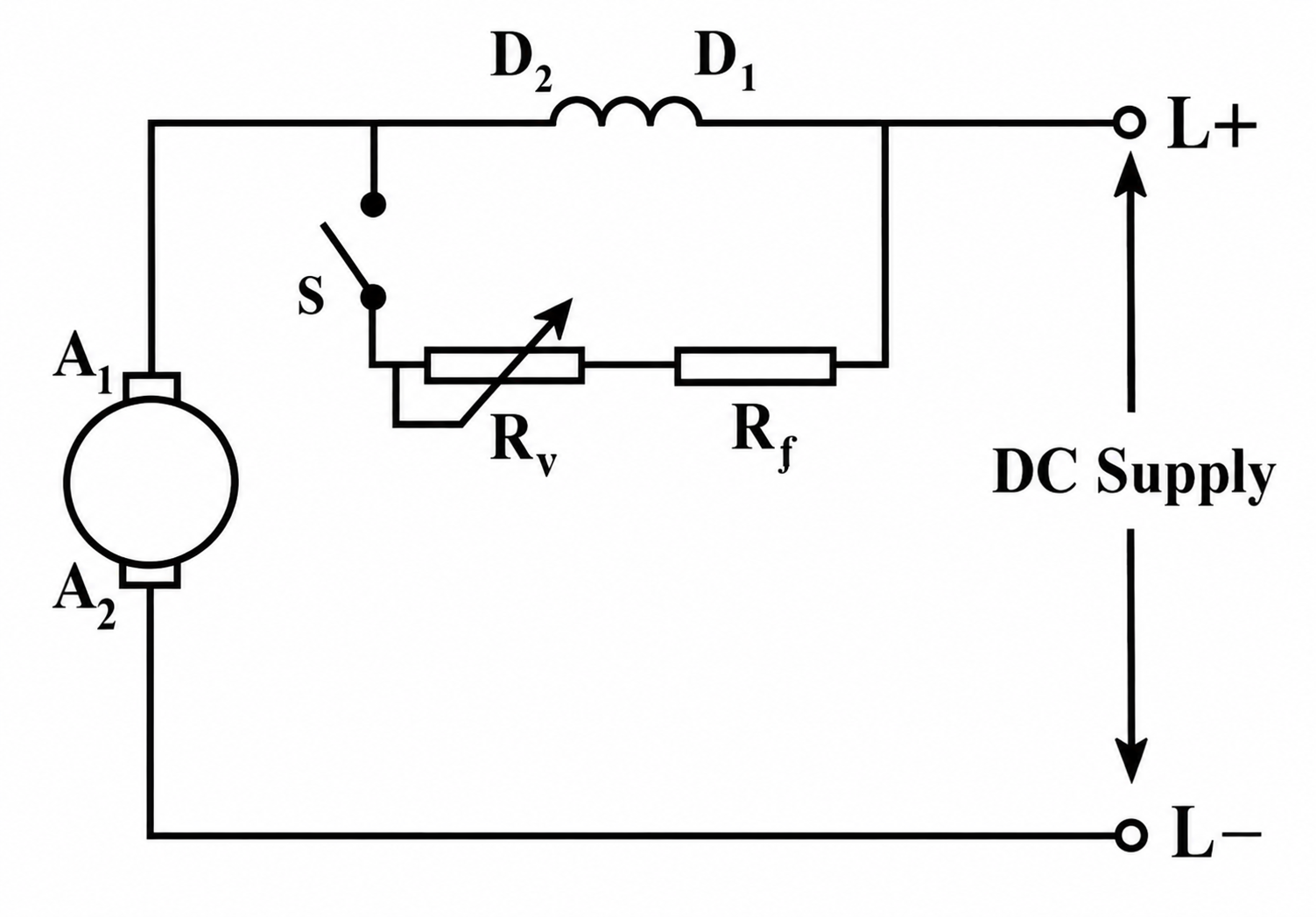
Field diverter method
Armature diverter method
Tapped Field Control
Resistance diverter control
To determine the speed control method for the DC motor shown in the diagram, we need to analyze the circuit components and their configuration.
Correct Option: A) Field diverter method
The no-load test, also known as the open-circuit test, is a crucial experiment performed on a transformer to determine specific parameters related to its core. During this test, the transformer's secondary winding is kept open, and the primary winding is supplied with its rated voltage at rated frequency. The current drawn by the primary winding under these conditions is primarily due to the magnetizing current and the current required to supply the core losses.
D) magnetising current and losses — As explained above, the no-load test directly measures the core losses (from the wattmeter reading) and allows for the calculation of the magnetizing current using the measured voltage and current.
This problem involves the fundamental principle of a transformer, which relates the ratio of the number of turns in the secondary and primary coils to the ratio of the electromotive forces (EMFs) induced in them. For an ideal transformer, the ratio of the secondary EMF to the primary EMF is equal to the ratio of the number of turns in the secondary coil to the number of turns in the primary coil.
Identify the given information:
Recall the transformer equation for EMFs and turns:
For an ideal transformer, the relationship between the primary and secondary voltages (EMFs) and the number of turns is given by:
\[ \frac{E_s}{E_p} = \frac{N_s}{N_p} \]Where:
Substitute the given values into the equation:
We are given \(N_s / N_p = 3\) and \(E_s = 600 \text{ V}\). We need to find \(E_p\).
\[ 3 = \frac{600 \text{ V}}{E_p} \]Solve for \(E_p\):
Rearrange the equation to solve for \(E_p\):
\[ E_p = \frac{600 \text{ V}}{3} \]\[ E_p = 200 \text{ V} \]
Correct Option: C) 200 V — The calculation shows that the EMF in the primary coil is 200 V, which is consistent with the step-up ratio of 3 for the secondary to primary turns.